Lime kiln

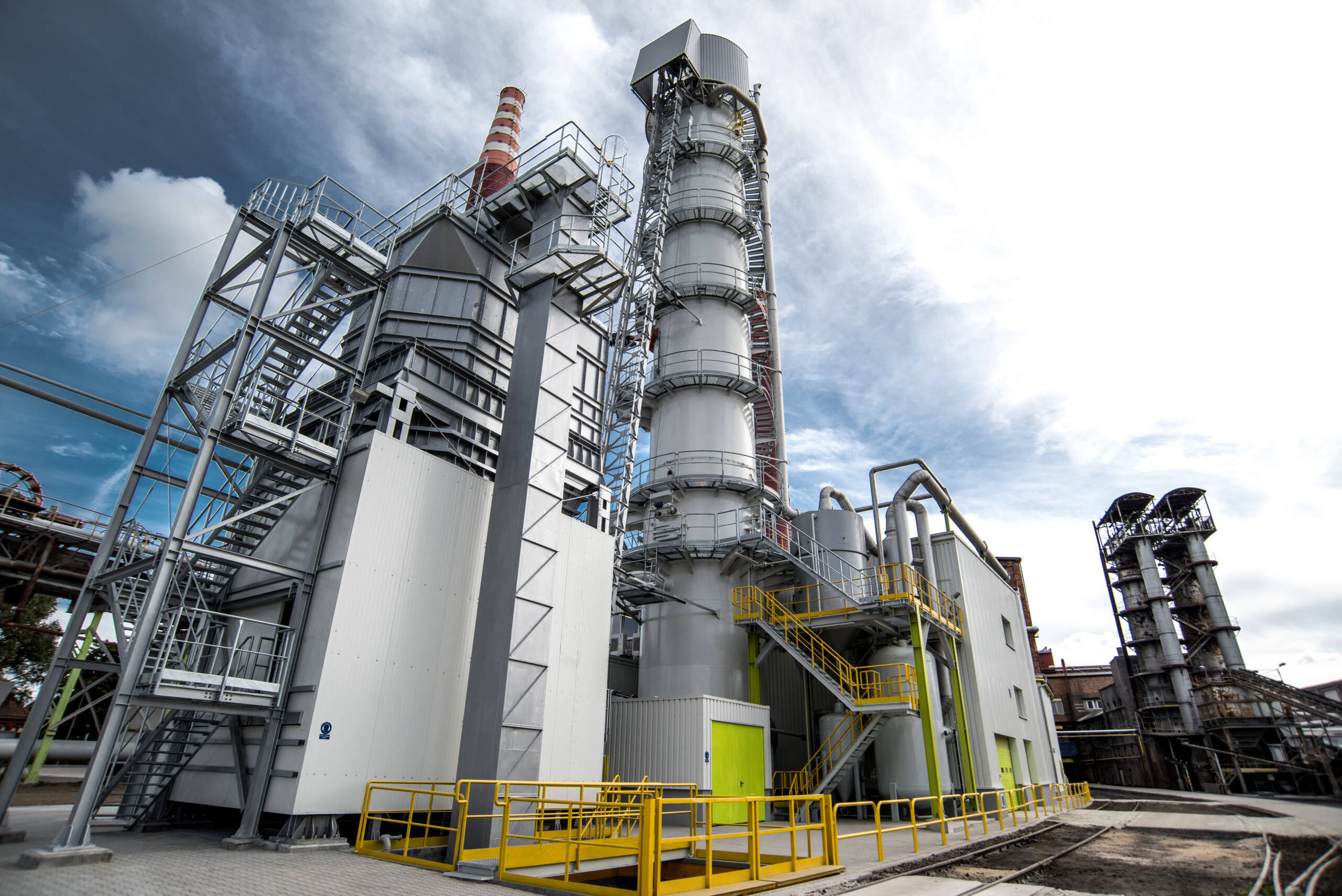
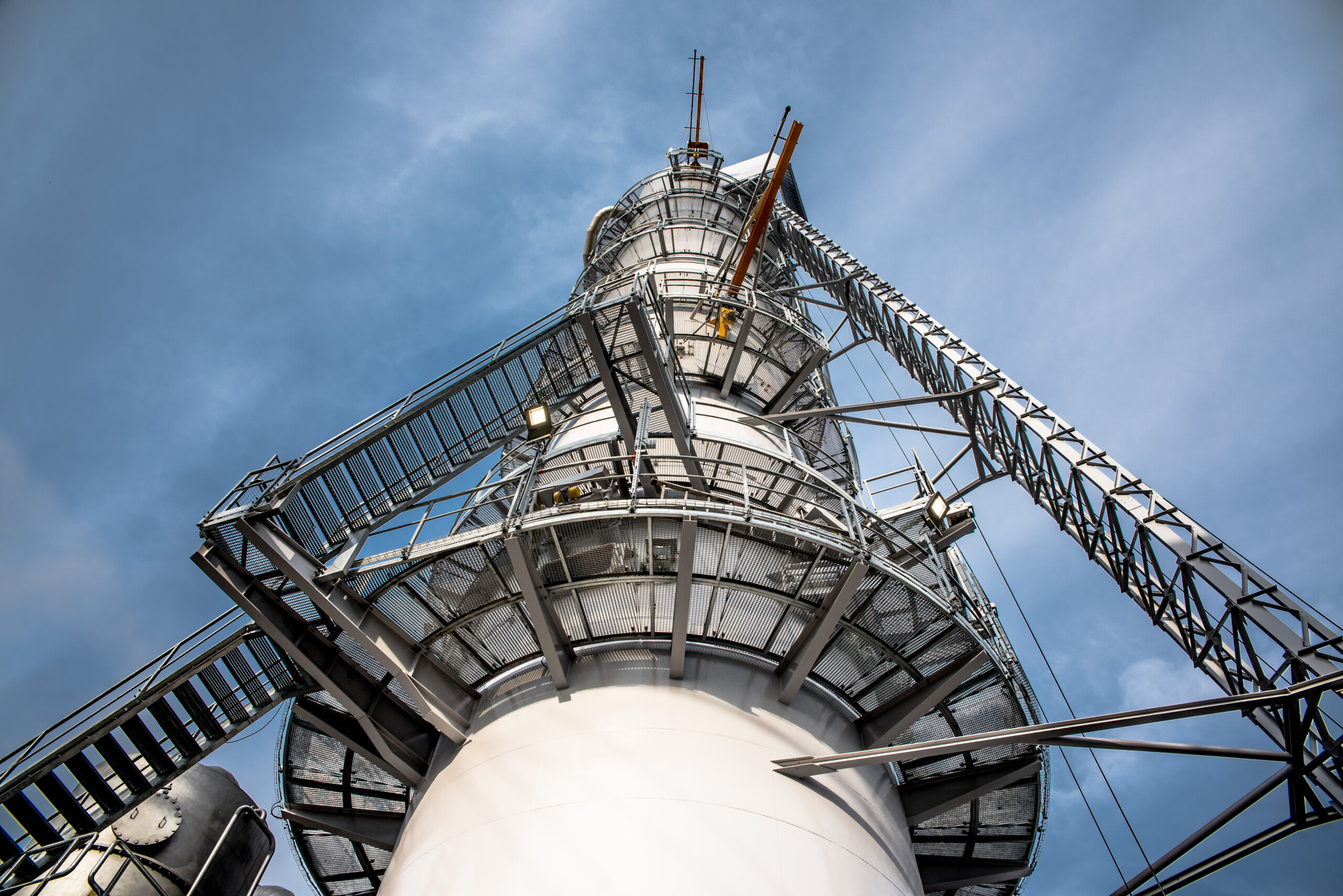
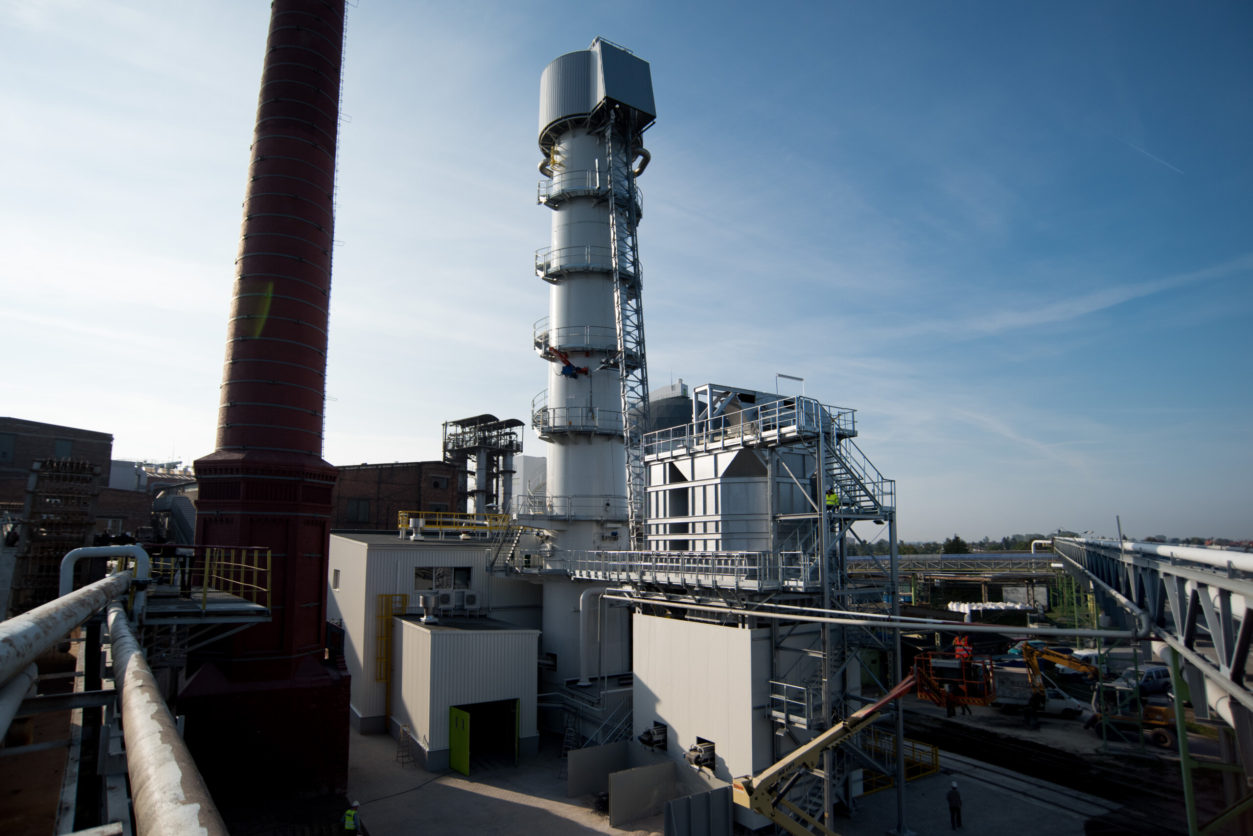
We are a manufacturer of shaft lime kilns for more than 60 years. A lime kiln is a unit in which low-reactive quicklime is produced through a calcination reaction. The secondary product is a gas which, depending on the technology, contains carbon dioxide (CO2) in an amount of approximately 32÷40%. The fuel used to generate and maintain the temperature of the calcination process in our kilns is both coke and anthracite. We offer both vacuum and overpressure kilns. These units are commonly used in lime and chemical plants as well as sugar plants. We supply and assemble complete units including operating platforms, refractory, automation and control elements. We also have our customised solution of a gas-fired shaft lime kiln.
Kiln loading system
The previously prepared mixture of limestone and coke/anthracite is loaded into a bucket for transport to the top of the kiln. The skip is a structure made of steel profiles serving as a route for the bucket with the batch mixture. Sensors are placed along the skip’s route to signal the position of the bucket during movement. They are also used to change the speed of the bucket, which is reduced at the bottom and top of the skip. Our winch has a double-rope system, which protects the bucket from uncontrolled damage caused by rope breakage. The winch has additional protection in the form of an encoder that counts the number of engine revolutions and thus monitors the current position of the bucket. The size of the skip, bucket and winch is selected according to the designed output of the lime kiln. The entire process is controlled by a central computer which, upon receiving information on the level of the kiln’s filling with the batch mix, activates the kiln charging cycle.


Upper closure
The shaft kiln charging solution we use has been in operation in many lime kilns for several decades. It is used in both overpressure and underpressure kilns. It is equipped with an upper sealing flap and a cone that functions both as a separation of the atmosphere in the kiln from the surroundings and as an element for distributing the lime in the kiln shaft in an appropriate manner. When the top flap is opened, the mixture is introduced into the charging chamber of the top seal. Closing the top flap seals the upper part of the kiln which allows for the rotation of the cone to start up, moving the batch in such a way as to discharge the mixture in a different part of the kiln shaft after opening the cone. This ensures that the mixture is properly distributed for the calcination process. The upper closure has a normal operation mode and a loading mode. In the kiln pre-loading mode, the loading chamber of the upper closure, together with the cone, descends into the furnace shaft to prevent damage to the furnace lining. Our solution makes it possible to control the top closure in both automatic and manual mode. Installed sensors continuously monitor the position of all components and the corresponding rope tension. The upper flap and cone are controlled using a hydraulic unit that is supplied with the unit.
Lime extraction system from the kiln shaft
In the lower part of the process chamber of the lime kiln just above the lime storage tank, a distribution cross with extraction vibrators is installed. The lime extraction process from the kiln shaft is carried out in this part of the kiln. The extraction vibrators we manufacture are a proven solution based on the use of vibration drives. The number of vibrators depends on the capacity of the lime kiln. The capacity of each vibrator is adjusted by changing the vibration frequency. In this way, it is possible to modulate the speed of movement of the charge in different parts of the horizontal section of the kiln. This is very useful when the firing zone in the kiln is not uniformly distributed and corrective action is required. Each vibrator is equipped with an inspection hatch for monitoring the correct functioning of the device and the lime extraction process. As an option, signalling devices are fitted to monitor the flow of lime through each vibrator.


Kiln air supply system
As most of the lime kilns that we manufacture are overpressure units, we have developed our own air distribution system for the kiln process chamber. It is responsible for transporting and ensuring adequate distribution of process and cooling air across the kiln chamber. The overpressure in the kiln is generated by an inverter-controlled fan, whereby the desired pressure value is set and maintained. The air pipe transports the medium to the distribution cone installed on the lime distribution cross section.
Kiln bottom hopper
Each of our kilns is equipped as standard with a quicklime kiln hopper. Its capacity provides a lime buffer in the event of short maintenance work on downstream equipment. It also allows the kiln capacity to be temporarily increased or decreased. The tank is equipped with radar sensors measuring the filling level of the tank. An installed maintenance manhole allows inspections and work to be carried out while the kiln is not in operation.
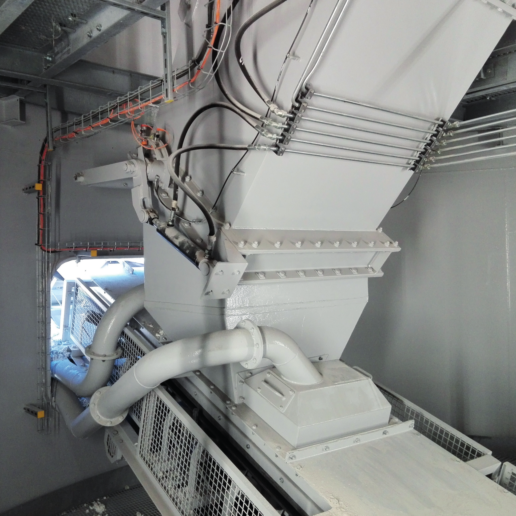
Sluice system (lime extraction)
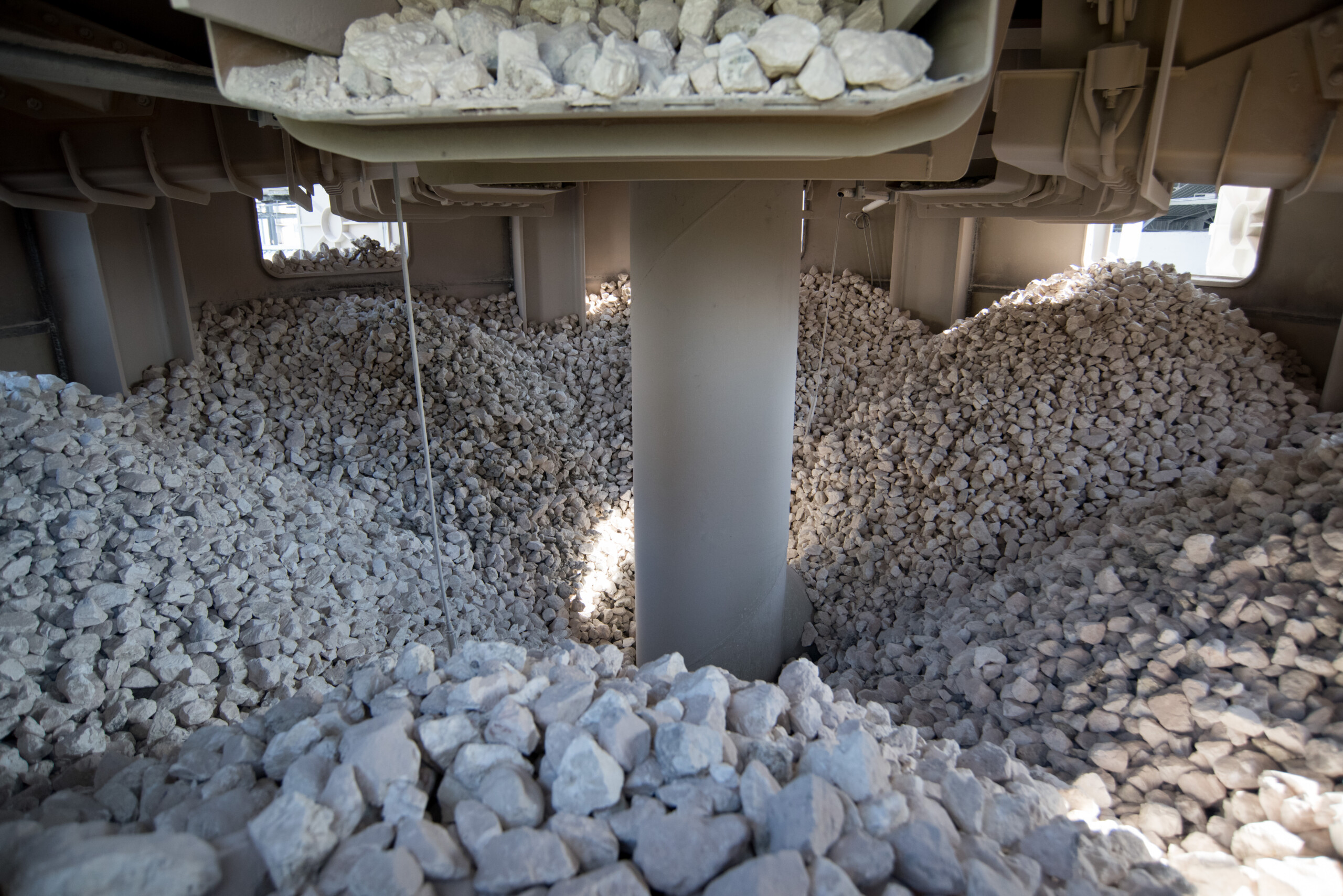
We use our proven lime sluice system to ensure an appropriate lime dosing process. The unit is available as a two or three flap version depending on whether you also plan to transport the lime outside the main process line. Hydraulic cylinders coupled with a hydraulic unit are mounted on both the lime feeder and flaps. In addition to dosing, the lime sluice system also has the task of sealing the bottom of the kiln, which is important for operational safety in overpressure kilns. The reciprocating feeder installed in the top of the lime sluice system is responsible for dosing the lime into the intermediate chamber of the sluice system. The unit is fitted as standard with sensors to indicate errors in the operation of individual components and the open or closed position of each sluice.

